
User Guide & FAQ
Telosolid turns a plain-language description — or a photo — of a mechanical part into a real 3D model you can view and download as STL or STEP, plus 2D DXF drawings for laser cutting and waterjet, and a dimensioned manufacturing drawing you can edit before sending it to a shop. Every build is kept, so you can go back to an earlier one, and any design can be shared with a view-only link. This guide covers everything you can do as a user — from your first sign-in to getting clean, manufacturable files.
Quick tour of the screen
Here's the Telosolid Studio workspace. The numbered markers point to the controls you'll use most — the legend below explains each one.

- Design Pilot / History / 3D tabs — switch between your active design chat, your saved past sessions, and the 3D view (handy on a phone). The green dot means the AI is online.
- The conversation — describe your part and refine it here. Every answer, build and error stays in the session, so you can come back to it later.
- Prompt box — type your description, or dictate with the microphone. The icons underneath attach a reference photo (camera), attach what the 3D view currently shows so the AI sees what you mean (eye), and import a STEP file to view and work from (cube).
- New Design / Send — Send submits your prompt; + New Design starts a fresh part in a new session.
- View buttons (ISO / Top / Front / Side / Fit) — snap the camera to standard engineering views. Fit zooms to whatever is visible, so hiding all but one part and pressing Fit frames just that part.
- Measure — click two points on the model to measure the distance between them.
- Units (mm / in) — switch the measurement readout between millimetres and inches. A new drawing starts in the same units.
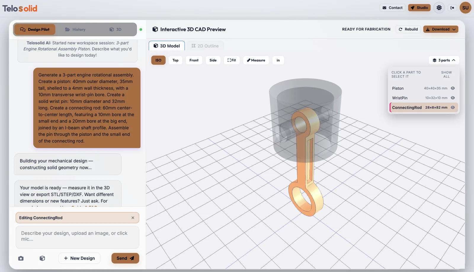
- Parts panel — appears when a design has more than one part. Click a part to select it (its name then appears as an "Editing" chip, and your next message changes that part only); use the eye icons, Show all and Hide all to choose what is visible. Downloads include only the visible parts. Check fit, under the list, says whether two parts clash, touch or clear (see Checking that two parts fit).
- 3D Model / Drawing tabs — Drawing is the dimensioned manufacturing sheet, which you can edit (see the Drawing tab). A 2D Outline tab also appears when you design from a photo: Telosolid traces a clean outline of the part and shows it there. Switching tabs never discards anything.
- Build status — Ready for Fabrication when the model built and passed its geometry checks; otherwise it tells you what happened.
- Rebuild — build the current design again. You rarely need it: reopening a session puts its last model back on screen by itself.
- Download — every file for the current design: STL and STEP for the 3D model, a DXF of the view you are looking at, the DXF of a traced 2D outline, and the manufacturing drawing PDF.
- Designs left — how much of your plan's allowance remains this period.
- 3D preview — your model. Drag to orbit, scroll to zoom, right-drag (or two fingers) to pan.
Two buttons sit between Rebuild and Download that are newer than the screenshot: Builds lists every build of the design so you can go back to an earlier one (see Build history), and Share makes a view-only link to it (see Sharing a design).
1. Getting started
Telosolid runs entirely in your browser. There is nothing to install.
- Create an account. Sign up with Google, or with your email and a password — there is no username to choose. Then click the link we email you to verify the address.
- Sign in with your email and you'll land in your workspace.
- Make your first part. The first time in, a card offers three starting points — a mounting plate, a pipe bracket and a box with a lid. Tapping one puts its description in the message box; change the sizes to yours and press Send. Or ignore them and describe your own part. Once it is built, a short message shows what to try next.
Tip: Trouble signing in? Check that you've verified your email first, then reach out via the contact form.
2. Your workspace & sessions
Each design lives in its own session — a conversation plus the model it produced. Your sessions are saved to your account, so you can close the tab and pick up later.
Working with sessions
- New session — start a fresh part. Use one session per part for the cleanest results.
- Switch — select any session from the sidebar to return to that design and its history.
- Rename — sessions are auto-named from your prompt. To rename, use the rename control next to the session and type a new name (works on mobile too).
- Delete — remove a session you no longer need.
Reopening a session puts its last model back on screen, ready to download, without building it again.
Big designs: you don't have to wait
Most designs arrive in well under a minute. A large one — several parts, many features, a long description — can take a few minutes. If a request is still running after a minute, the chat tells you so, and you are free to go:
- Open another chat and carry on there, or close the browser altogether. The design keeps being worked on and is saved to its session when it is ready.
- Come back to that chat and the model builds by itself. There is no need to press Rebuild.
- Don't send the message again. The first request is still running, and a second one would be a second design taken from your allowance.
If a design really could not be finished, the chat says so; try again with the main part first and add the rest in follow-up messages.
3. How to prompt (best practice)
Telosolid works best when you describe a part the way you'd brief a machinist: what it is, its dimensions, and its features. Clear, specific prompts produce clean geometry on the first try.
Do
- State real dimensions and units — e.g. "a 60 mm × 40 mm × 5 mm plate" or "4 inches". Telosolid can design in any units you specify; if no unit is provided, millimetres (mm) are used by default.
- Describe features explicitly — bores, holes, fillets, chamfers, counterbores, wall thickness, bolt circles: "a central 10 mm bore and four M4 holes on a 50 mm bolt circle".
- Say which parts are separate. A design can hold several parts — "a housing and a separate lid" gives you two, each named and selectable. Be explicit about what is a distinct part, because holes, fillets and bosses are features of one part rather than parts of their own. See Designs made of several parts.
- Iterate in the same session. Follow up with refinements: "make it 3 mm thicker", "add a 2 mm fillet to the top edges". It remembers the current design.
Avoid
- Vague briefs ("make a cool bracket") — give size and features.
- Full assemblies, threads modelled as real helices on tiny fasteners, or organic/freeform surfaces — these are mechanical-solid strengths, not sculpting.
Example prompt: "A motor spacer plate, 56 mm square, 6 mm thick, with a 22 mm central bore, four 4.5 mm mounting holes 5 mm in from each corner, and a 1 mm chamfer on the top outer edge."
Designing from a photo or sketch
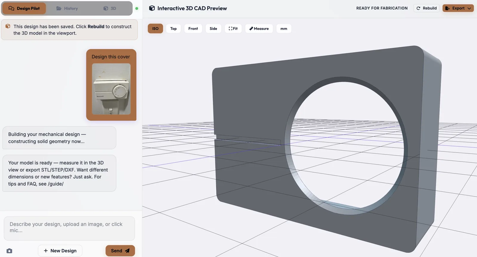
Attach a reference image with the camera icon in the prompt box — a photo of a real part, a hand sketch, or a dimensioned drawing. Telosolid identifies the object and its features from the image and builds to match it, so a good image does much of the describing for you. You can attach more than one view (for example, front and side), and large photos are downscaled automatically.
For the best results, use an image that is:
- One part, filling the frame — a single object against a plain, uncluttered background. Crop out everything else.
- Sharp and evenly lit — in focus, no motion blur, and minimal shadows, reflections, or glare (matte parts photograph better than shiny ones).
- Shot straight‑on — a square front, top, or side view reads far better than a dramatic perspective angle. If the shape isn't clear from one view, attach a couple of orthogonal views.
- High‑contrast — the part should stand out clearly from the background.
Getting the size right — the single most useful image tip: a photo has no built‑in scale, so Telosolid can only estimate real dimensions from what the object looks like. To lock the size, do any one of these:
- Put a ruler or calipers in the shot, laid alongside the part and readable.
- Include a common object for scale (a coin, a standard bolt) if no ruler is handy.
- Annotate the image with the key dimensions, or
- State the critical dimension in your text — e.g. "the plate is 80 mm wide". Your text always overrides whatever the image implies, so one real measurement anchors the whole part.
You also get a 2D outline. Whenever you attach a photo of a real part, Telosolid traces its silhouette into a clean DXF alongside the 3D build — see 2D drawings & outlines. For flat parts (brackets, gaskets, plates) you can also build the model from that outline, as a second build next to the one made from the photo.
Sketches and drawings work very well — often better than photos — because you can label them. A dimensioned orthographic sketch (front / top / side with lengths, diameters, and hole positions written on it) gives Telosolid exact numbers to build from.
Avoid: busy backgrounds, several parts in one photo, extreme or artistic angles, a tiny part lost in a large frame, and screenshots cluttered with UI, watermarks, or arrows that aren't dimensions.
4. Checking & correcting a build
It checks its own work
When a build finishes, Telosolid looks at it from four sides (isometric, front, top and right, with the measured size) and compares that with what you asked for. You will see “Checking the build against your request…” in the chat for a few seconds.
- If it matches, you are told so and nothing changes.
- If something clearly contradicts your request (a missing hole, the wrong count, a size well off), it rebuilds once with a correction. The correction replaces your model only if it builds; otherwise your original stays and the chat says so.
It checks once per design, and it is cautious by design: it only flags clear contradictions of what you actually asked for, never matters of taste or details you did not specify.
Show it what you see
When something is still not right, the quickest way to explain it is to show it. Rotate the model to the angle that shows the problem, then press the eye icon next to the camera in the prompt box. The current view, plus front, top and right views and the part’s size, is attached to your message, marked Current design view. Then say what is wrong:
Example: rotate to show the underside, press the eye, and type “the two mounting holes should go through the flange, not the base”.
Telosolid reads the picture as your current design, not as a new reference to copy, so your words decide what changes and everything else stays as it is. If you have a part selected in a multi-part design, it is highlighted in the picture too. The eye is only available once a model is on screen.
5. Viewing your model
When generation finishes, your part compiles and appears in the 3D viewport. Compilation runs on a dedicated engine that may take a few extra seconds the first time after a quiet period — this is normal.
- Orbit — click and drag to rotate.
- Zoom — scroll or pinch.
- Pan — drag with the right mouse button (or two fingers).
- View modes — switch between shaded and wireframe-style views to inspect geometry.
- Standard views — ISO / Top / Front / Side snap the camera to engineering views, and Fit zooms to whatever is visible without changing the angle you are looking from. These follow the normal CAD convention (Z up) and match the DXF drawings exactly: the Top view on screen is the same view you get from the Top DXF.
Above the preview, the Drawing tab holds the manufacturing drawing of the part, and a 2D Outline tab appears when you designed from a photo — see Drawings below.
If your design has more than one part, a parts panel appears at the top right of the viewport — see Designs made of several parts.
6. Build history: going back to an earlier build
Every time a design builds, the build is kept. The Builds button next to Rebuild opens the list, and once there are two or more it shows where you are — 3 / 5 means you are on build 3 of 5. The list reads Build 1, Build 2 and so on, in the order they were made, each with the request that produced it. The current one is marked Current in green.
- Pick a build to look at it. It loads in the viewer and a banner says which build you are viewing. While it is on screen the chat is paused, so a request can never change a design you are not looking at.
- Restore build N makes it the current design: your next request builds on it, and downloads and share links use it. Restoring costs nothing — no AI and no new build.
- Back to current leaves things exactly as they were.
Numbers only go up when something new is built. Restoring an earlier build does not add one, and pressing Rebuild rebuilds the current build in place under the same number. A request made after a restore becomes the next number, so nothing is ever overwritten.
To show a design to someone else, see Sharing a design: the link always shows the current build.
7. Designs made of several parts
A design can be more than one part. Ask for a housing and a separate lid and you get two parts, not one fused lump — each with its own name, listed in the parts panel at the top right of the viewport.
Whether a design splits is a question about the object, not about wording. Things that are manufactured separately and could be picked up one at a time are separate parts. Holes, fillets, ribs and bosses are features of a part, so a bracket with four mounting holes stays a single part.
- Select a part — click its row, or click the part itself in the viewport. It highlights, and the rest of the model fades back so you can see what you picked.
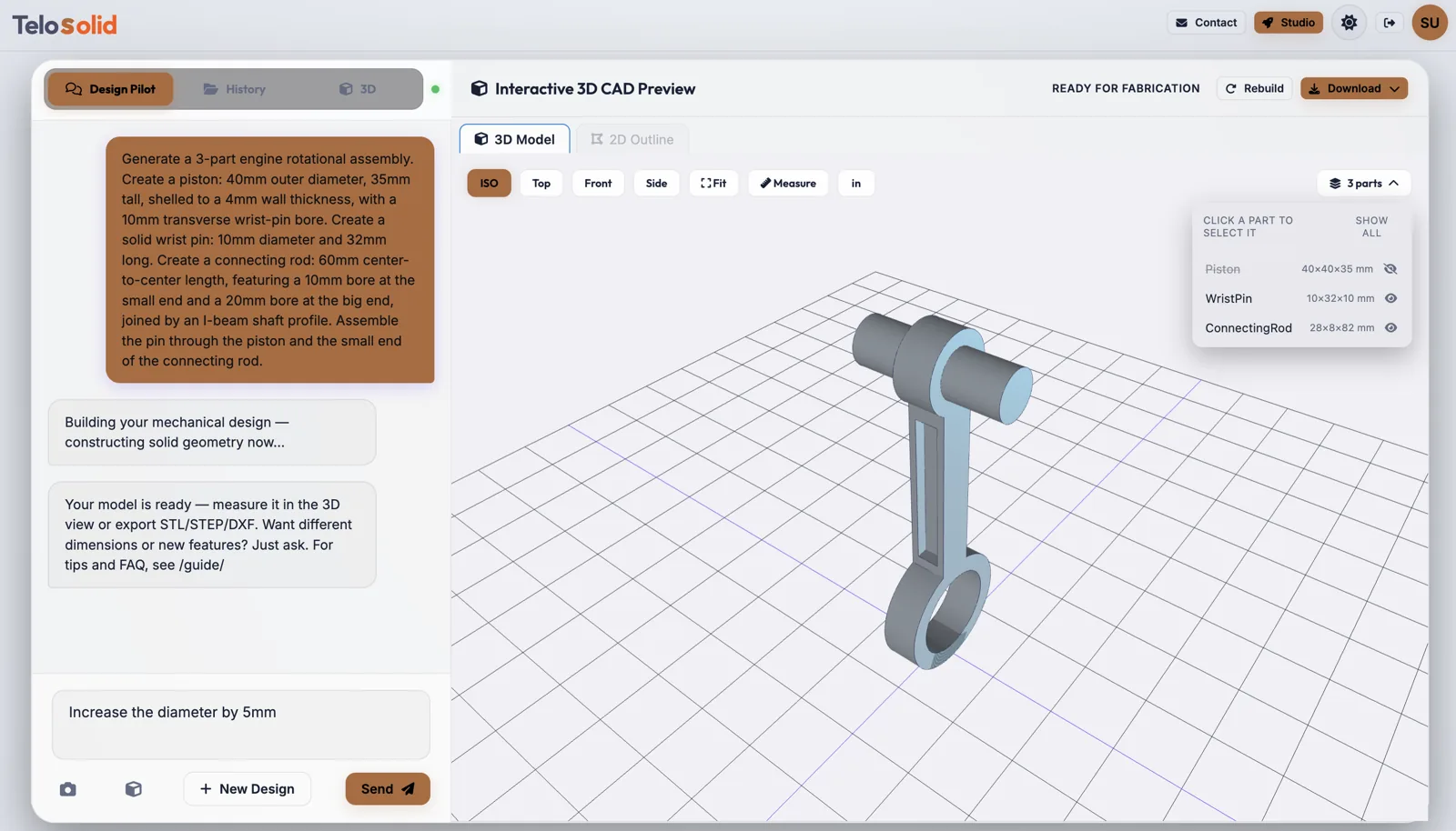
- Hide a part — the eye icon on its row. Useful for seeing inside an assembly, and it changes what you export (below).
- Show all / Hide all — at the top of the panel. To look at one part on its own, press Hide all, unhide the part you want, then press Fit to zoom to it. Each button greys out when it would do nothing.
- Collapse the panel — the header button shrinks it to a single “N parts” chip so it is out of the way of the model.
Changing one part
With a part selected, a chip above the message box says Editing <part>. Your next message applies to that part alone — “make the walls 8 mm thick” thickens the housing and leaves the lid exactly as it was. Dismiss the chip (or click the selected row again) to go back to changing the whole design.
Checking that two parts fit
Open the parts panel, press Check fit under the list of parts, choose two, and press Check. If a part is selected it is chosen first. A few seconds later you get one of three answers:
- Clash — the parts share material. The overlap is shown in red in the viewport, with its volume, so you can see where they collide.
- Touch — they meet with no gap and no overlap, as faces modelled flush do.
- Clear — the smallest gap between them, drawn as a line between the two closest points.
It checks the parts as they sit, not in motion, and it states the number rather than a pass or a fail: how much clearance a print, a sliding fit or a press fit needs depends on your process, so that judgement stays yours. A check costs nothing from your monthly allowance. Close it, or rebuild, and the highlight goes away.
What you see is what you export
This is the rule worth remembering: every export contains exactly the parts visible on screen.
- One part selected → you get that part.
- Nothing selected → you get every part that is still visible.
- A part hidden → it is absent from the STL, the STEP, the DXF and the drawing alike.
It applies to all four formats, so a drawing of two parts out of five is made the same way as a download of them: hide the rest, then export. If everything is hidden, the export refuses rather than quietly giving you the whole model.
8. Importing a STEP file
You can bring in a solid built somewhere else. Use the import button next to the camera icon below the message box and choose a .step or .stp file.
Once it loads it behaves like any other model: orbit it, measure it, pick its parts apart, hide what you do not need, and export what is left as STL, STEP, DXF or a dimensioned drawing.
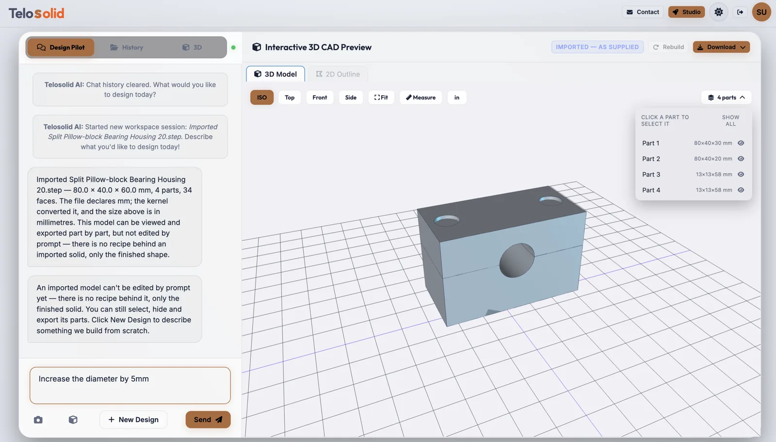
What an imported model cannot do is change by asking. A design built here has a recipe behind it, which is what makes “make it 10 mm thicker” possible. An imported STEP is the finished shape with no history, so there is nothing to edit. Telosolid says so rather than quietly building you something unrelated, and your model stays on screen.
- STEP only — an STL is a mesh of triangles rather than a solid, so it cannot be imported as one.
- Imported parts are listed as Part 1, Part 2… with their sizes. Most STEP files do not carry usable part names; designs built here do, which is why those are named properly.
- Imports count against a monthly allowance that depends on your plan — see Usage, plans & limits.
9. Drawings: the Drawing tab, DXF & outlines
Telosolid produces three different 2D deliverables. A manufacturing drawing is a dimensioned PDF sheet for a machinist. A projected DXF is vector geometry for a laser cutter, waterjet, router, or plotter. A traced outline is the silhouette of a part in a photo. They answer different questions, so it is worth knowing which one you want.
Manufacturing drawings: the Drawing tab
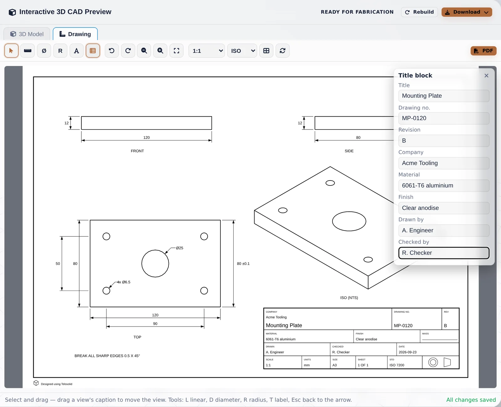
Click the Drawing tab above the 3D preview (or Download → Open drawing editor). The first time, the part is measured and laid out on an A3 sheet — front, top, side and isometric views, dimensioned automatically from the solid, with a standards title block. That takes a few seconds. After that the drawing is yours to adjust, and every change is saved automatically (the status at the bottom right says All changes saved).
What is dimensioned automatically: overall width, height and depth; hole and bore
diameters, grouped when several are identical (4x Ø6.5); and hole-to-hole spacing. Every
value is measured from the real geometry.
The toolbar
- Arrow V — select and move. Drag a dimension to move its line or its label; drag a label; drag a view’s caption (FRONT, TOP…) to move the whole view with all its dimensions.
- Linear dimension L — click two points on the part (clicks snap to corners, edges and hole centres), then click where the dimension line should go. Placing it above or below makes it horizontal, to the side makes it vertical, and between the points makes it aligned.
- Diameter D and Radius R — click a hole or arc; a callout is added and you can drag it where it reads best.
- Label T — click where a note goes, then type it in the panel that opens. Add leader gives it an arrow pointing at something.
- Title block — opens the title-block fields (the button lights up while open).
- Undo / Redo Ctrl+Z / Ctrl+Shift+Z, zoom and fit.
- Scale, ISO / ASME and mm / in — change the sheet scale, the projection convention, or the units the dimensions are printed in; the views re-arrange around their dimensions. Inches are decimal inches to three places (4.724, .250), and a new sheet starts in the units the 3D view is showing.
- Arrange — tidy the views back into a standard layout. Reset — replace your dimensions with the automatic ones (labels and title block are kept; you are asked first).
- PDF — export the sheet exactly as shown.
Getting in and out of a tool: each tool places one item and returns to the arrow. Hold Shift while placing to add several in a row. To leave a tool without placing anything, press Esc, right-click, click empty paper, or click the tool button again.
Editing a dimension or label
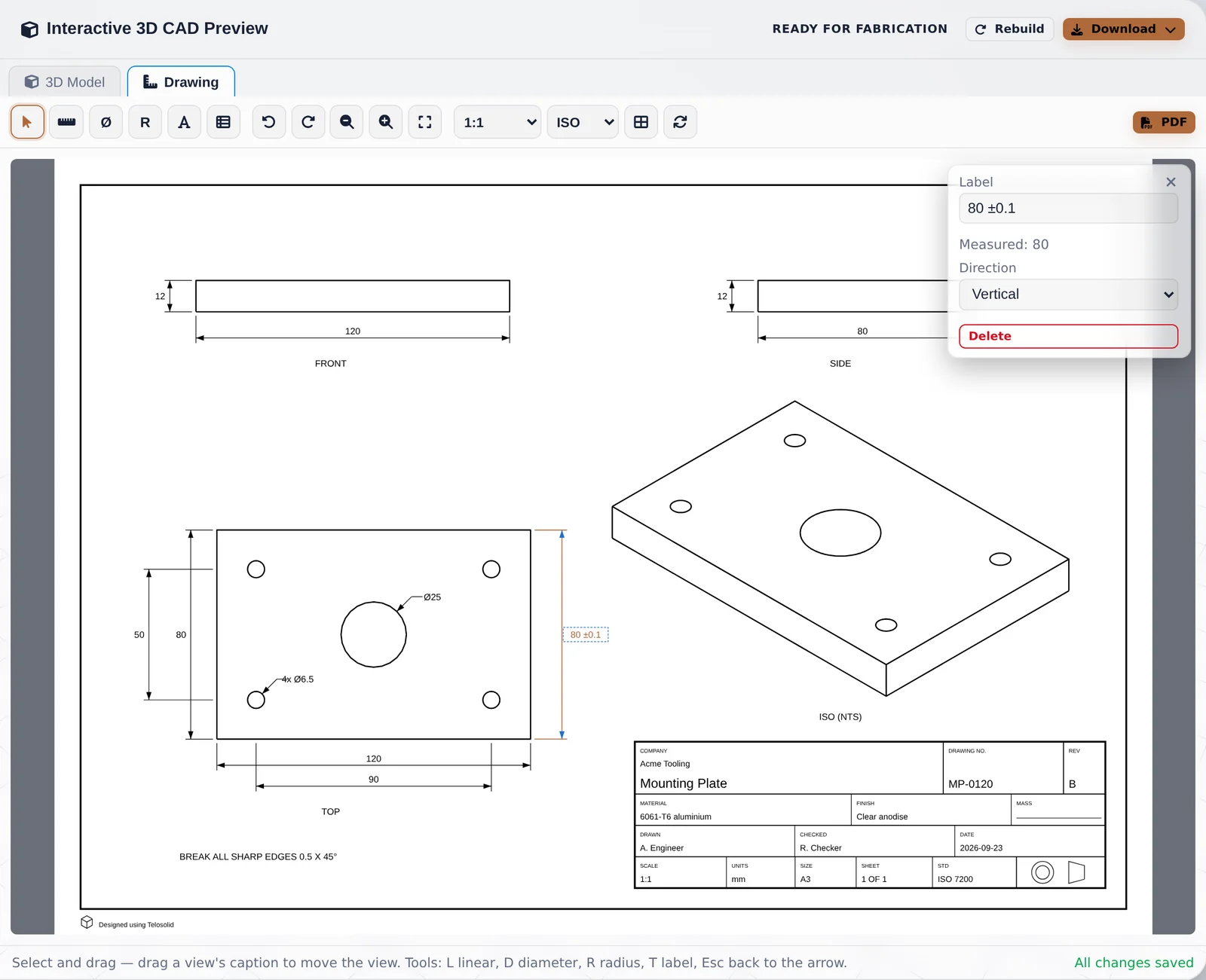
Click it to select it; a small panel opens over the corner of the sheet. There you can:
- Replace the text, for a tolerance or a reference mark — for example
40 ±0.1or(40). Leave it empty to show the measured value, which the panel always shows for reference. Editing the text changes what is printed, never what was measured. - Switch a linear dimension between horizontal, vertical and aligned; switch diameter and radius; add a
count such as
4x. - Delete it (or press Delete).
Close the panel with its × to see the whole sheet again.
The title block
Press the Title block button and fill in what nothing can work out from geometry, and a shop asks for before it quotes: title, drawing number, revision, company, material, finish, drawn by and checked by. Blank fields print as empty labelled boxes, so the reader knows to ask. Choose ISO (first-angle) or ASME (third-angle) to match whoever will read the sheet: they are mirror-image conventions, and the sheet states which it uses.
Before you export
Labels that overlap are outlined in red, and the count is shown at the bottom. Move them apart before exporting; the PDF tells you too if any are still overlapping. The automatic layout leaves off a dimension it cannot place legibly — add it back where it reads.
Coming back later, and after a rebuild
The drawing is saved with the design. Reopen the session next week and the Drawing tab shows it exactly as you left it. If you change the design and rebuild, the new build gets a fresh drawing that keeps your title block and notes but measures the new geometry — old dimensions of a part that has changed would be wrong. With parts hidden or one part selected, the Drawing tab draws exactly what is on screen.
If the same drawing is open in two windows, the second one to save is asked to reload rather than silently overwriting the first.
On a phone or tablet the toolbar wraps onto two rows; pinch with two fingers to zoom and drag to pan. Detailed editing is easiest on a larger screen.
Not added automatically, on purpose: tolerances, GD&T, surface-finish symbols, section views, thread callouts and chamfer notes. Those are engineering decisions, not measurements. Add tolerances and notes yourself with label text and notes, where they are clearly your decisions.
Projected DXF (vector geometry)
The two DXF routes below download as DXF, which opens in any CAD or CAM package and drives laser cutters, waterjets, routers, and plotters.
Once a model is built, Telosolid can flatten it into a true orthographic view — any view, not just the standard ones. Set the model to the angle you want using the view buttons above the preview (ISO, Top, Front, Side) or just by dragging to rotate it. Then open Download (top right) and choose Download this view.
What you see is what you get: the drawing comes out at the angle and orientation on your screen. Pick one
of the four standard views first and you get exactly that classic engineering view, named accordingly
(_top.dxf, _front.dxf, and so on).
Every view is projected from the real solid geometry, so edges, holes and curved silhouettes land exactly where they are on the model — the DXF is dimensionally correct, not a screenshot.
Outlines traced from a photo
When you attach a photo of a real part, Telosolid also separates the part from its background and traces its silhouette into a clean 2D outline. This runs alongside the 3D build, so it never holds your design up, and it appears in the 2D Outline tab above the preview (a dot marks a new one).
In that tab you can:
- Photo — show or hide the original photo behind the traced line, to check how faithfully it followed the edge.
- Zoom / Fit — inspect the trace closely; the outline stays locked to the photo.
- Improve trace — if the line is too rough, too smooth, or picked up specks, adjust Detail and Specks, toggle Include holes, then Re-trace photo.
- Download DXF — save the outline (also in the top-right Download menu).
Flat parts can be built from the outline. If the part is flat — a bracket, gasket, plate, or panel — its silhouette is its shape. Telosolid builds the 3D model from the photo straight away; if the traced profile matches your part better, set Part is: Flat and choose Construct 3D geometry. That model is added as a new build, so you can compare the two and switch back under Builds. For parts whose depth varies (a drill body, a bottle), leave it on 3D object: the outline stays a 2D deliverable.
For a clean trace, the same photo advice applies as for designing: one part filling the frame, on a plain high-contrast background, sharp and evenly lit, shot straight-on. A busy background is the most common cause of a messy outline.
10. When a build fails
Sometimes a design won't compile on the first attempt — a dimension conflicts, or a feature can't be built as described. Telosolid automatically tries to repair and rebuild once. If it still fails, you are in control:
Most useful tip in this guide: if a build fails, just ask the chat to fix it — type something like "that failed to build, please fix the error and try again". Telosolid will analyse the error and attempt a corrected build. You can repeat this, refining as you go.
What helps the fix succeed
- Loosen the conflict. If a hole is larger than the wall around it, say so: "the bore is too big for the body — reduce the bore to 18 mm".
- Simplify, then add back. Get the base solid building first, then add fillets, chamfers, and holes in follow-up messages.
- Be specific about the change rather than re-describing the whole part.
11. Downloading files
Everything for the current design lives under one Download button at the top right of the workspace. Items appear as they become available, and files are tied to your account.
- STL — a mesh of the surface. Best for 3D printing and quick visual sharing. Not editable as parametric geometry.
- STEP — true solid (B-rep) geometry. Best for CAD/CAM: import into Fusion, SolidWorks, Onshape, etc., and for machining/manufacturing.
- DXF (2D drawing) — orthographic Top / Front / Side / Iso views projected from your 3D model. Useful for laser cutting, waterjet, and shop drawings.
- DXF (2D outline) — the silhouette traced from your photo, when you designed from one. Also available in the 2D Outline tab.
- PDF (manufacturing drawing) — exported from the Drawing tab, with your edits. Open drawing editor in this menu takes you there.
Rule of thumb: printing → STL, machining or further CAD work → STEP, flat-sheet cutting or shop drawings → DXF.
On a design with several parts, every download contains exactly what is visible in the viewport — see what you see is what you export. Files are named after your design, with the part appended when one is selected, so Pump Housing Rev C - Lid.step arrives ready to send on. Rename the design in History and the downloads follow that name.
13. Usage, plans & limits
Generation uses an AI allowance shown by the designs left meter at the top of the app (for example 4 designs left). Each design and each fix-and-retry consumes some of it. Looking at or restoring an earlier build, sharing a link, and copying a shared design use none.
- Running low? The meter warns you as you approach your limit.
- Need more? If subscription plans are available on your account, you can upgrade from the billing section to raise your monthly allowance and design count.
- Be efficient — clear prompts mean fewer rebuilds, which stretches your allowance.
- Imported STEP files have their own monthly count, separate from the AI allowance — importing a solid costs no AI tokens, so the two are metered apart. A file refused on import is not counted and is not kept.
14. Account & security
- Forgot your password? Use the reset link on the sign-in page; we'll email you a secure reset.
- Sign in with your email. Accounts created before October 2026 can also use the username they chose then.
- Account settings — open the account menu (your initials, top right) and choose Account settings. Plans & billing, your password, product emails and cookie settings are all there.
- Change your password in Account settings. New passwords need at least 12 characters, and changing it signs you out everywhere for safety. Accounts created with Google have no password to change — use Forgot password on the sign-in page if you would like to add one.
- Download my data — under Your data and account in Account settings. Confirm with your password (or, for a Google account, by typing your email) and a ZIP file downloads with what your account holds: profile, settings, design sessions and chat history, builds with links to their files, billing status, sign-in and consent records, and the photos you attached in chat.
- Delete account — in the same place, confirmed the same way. It permanently deletes your designs and every file you built or uploaded, ends your share links, and cancels any subscription. It cannot be undone.
- Your data — prompts, designs, and files are tied to your account. Nobody else can see a design unless you share a link to it, and a link never shows your chat or prompts. See the Privacy Policy.
15. FAQ & troubleshooting
The first model after a while took longer — is something wrong?
My build keeps failing. What should I do?
Can I make an assembly with multiple parts?
What units does Telosolid use?
Which file should I download?
Can I get a 2D drawing (DXF) of my model?
What is the 2D Outline tab?
The traced outline doesn't look right. Can I fix it?
Can Telosolid build a flat part from its photo outline?
Can I get a proper manufacturing drawing to send to a machine shop?
Does the drawing include tolerances or GD&T?
What is the difference between a DXF and a manufacturing drawing?
I signed up but can't sign in.
Can I keep editing a design later?
A big design is taking a long time. Do I have to wait?
How do I go back to an earlier version of my design?
How do I share a design?
Can people with my link change or download my design?
Someone shared a design with me. Can I edit it?
Is my design data private?
Can I design from a photo or sketch?
How do I get the size right when I design from a photo?
What kind of image gives the best result?
Still stuck? Contact us — we're happy to help.
Launch Telosolid